File format history
- V1.0 - First version.
- V1.5 - Introduced in PCB Elegance 3.0, adds support for objects on specific inner layers, silkscreen on top an bottom layers, rotation of text at any angle, MemSize value. The Polygon section is added. The SilkScreenOffset section is depreciated.
- V2.0 - Introduced in PCB Elegance 3.5, adds support for SubPolygons (polygon cutouts).
About
This document describes the geometry files for PCB Elegance. Geometries are sometimes known as shapes and the two terms are equivalent in this document.
The file is binary with little endian byte order. The units are metric with 10 nm resolution. For example 1 mm is represented as 100000. Standard CAD X/Y axis where the coordinates increase towards up, right.
| Data type |
Size in bytes |
|---|
| char |
1 |
| int16 |
2 |
| int32 |
4 |
| float |
4 |
| double |
8 |
| Limits |
|
|---|
| MaxObjectsPerPin |
8192 |
| MaxNrPins |
8192 |
Structure
| Section |
Start address |
Contains |
|---|
| Header |
0x0000 |
1 Header record. |
| PlacementOutLines |
0x009C |
NrPlacementOutLines * Object records. |
| CompOutLines |
*CompOutLineOffset |
NrCompOutLines * Object records. |
| Pins |
*PinOffset |
NrPins * ObjectPin records. Each ObjectPin record is followed by NrPinObjects * Object records. |
| SilkScreenOutLines |
*SilkScreenOffset |
NrSilkScreenOutLines * Object records. |
| OtherObjects |
*OtherObjectsOffset |
NrOtherObjects * Object records. |
| Polygons |
*PolygonOffset |
See the Polygons section for details. |
PlacementOutLines section
Placement outline layer objects. This is a border around the geometry to indicate minimum placement distance from other geometries. Placement outlines always have a thickness of 0. There are four object types available for this layer.
OBJECT_LINE, OBJECT_RECT, OBJECT_CIRCLE records
| Address |
Size |
Type |
OBJECT_LINE |
OBJECT_RECT |
OBJECT_CIRCLE |
Notes |
|---|
| 0x00 |
4 |
int32 |
0x1000 |
0x1200 |
0x1300 |
ObjectType |
| 0x04 |
4 |
float |
X1 |
X |
X |
|
| 0x08 |
4 |
float |
Y1 |
Y |
Y |
|
| 0x0C |
4 |
float |
X2 |
Width |
CircleDiameter |
|
| 0x10 |
4 |
float |
Y2 |
Height |
CircleType |
|
| 0x14 |
4 |
float |
– |
– |
– |
Not used |
| 0x18 |
|
|
|
|
|
Record size |
OBJECT_ARC record
| Address |
Size |
Type |
OBJECT_ARC |
Notes |
|---|
| 0x00 |
4 |
int32 |
0x1400 |
ObjectType |
| 0x04 |
4 |
float |
X |
|
| 0x08 |
4 |
float |
Y |
|
| 0x0C |
4 |
float |
CircleWidth |
|
| 0x10 |
4 |
float |
CircleHeight |
|
| 0x14 |
4 |
float |
StartX |
|
| 0x18 |
4 |
float |
StartY |
|
| 0x1C |
4 |
float |
EndX |
|
| 0x20 |
4 |
float |
EndY |
|
| 0x24 |
4 |
float |
– |
Not used |
| 0x28 |
|
|
|
Record size |
CompOutLines section
Component outline layer objects. This is a for the mechanical drawing.
OBJECT_LINE, OBJECT_RECT, OBJECT_CIRCLE records
| Address |
Size |
Type |
OBJECT_LINE |
OBJECT_RECT |
OBJECT_CIRCLE |
Notes |
|---|
| 0x00 |
4 |
int32 |
0x1000 |
0x1200 |
0x1300 |
ObjectType |
| 0x04 |
4 |
float |
X1 |
X |
X |
|
| 0x08 |
4 |
float |
Y1 |
Y |
Y |
|
| 0x0C |
4 |
float |
X2 |
Width |
CircleDiameter |
|
| 0x10 |
4 |
float |
Y2 |
Height |
CircleType |
|
| 0x14 |
4 |
float |
Thickness |
Thickness |
Thickness |
|
| 0x18 |
|
|
|
|
|
Record size |
OBJECT_ARC record
| Address |
Size |
Type |
OBJECT_ARC |
Notes |
|---|
| 0x00 |
4 |
int32 |
0x1400 |
ObjectType |
| 0x04 |
4 |
float |
X |
|
| 0x08 |
4 |
float |
Y |
|
| 0x0C |
4 |
float |
CircleWidth |
|
| 0x10 |
4 |
float |
CircleHeight |
|
| 0x14 |
4 |
float |
StartX |
|
| 0x18 |
4 |
float |
StartY |
|
| 0x1C |
4 |
float |
EndX |
|
| 0x20 |
4 |
float |
EndY |
|
| 0x24 |
4 |
float |
Thickness |
|
| 0x28 |
|
|
|
Record size |
OBJECT_TEXT record
| Address |
Size |
Type |
OBJECT_TEXT |
Notes |
|---|
| 0x00 |
4 |
int32 |
0x1500 |
ObjectType |
| 0x04 |
4 |
float |
X |
|
| 0x08 |
4 |
float |
Y |
|
| 0x0C |
4 |
float |
Height |
|
| 0x10 |
4 |
float |
Rotation |
|
| 0x14 |
4 |
float |
Thickness |
|
| 0x18 |
64 |
char |
Text |
ASCII text |
| 0x58 |
|
|
|
Record size |
OBJECT_POLYGON, PIN_SMD_POLYGON records
| Address |
Size |
Type |
OBJECT_POLYGON, PIN_SMD_POLYGON |
Notes |
|---|
| 0x00 |
4 |
int32 |
0x1700, 0x09B0 |
ObjectType |
| 0x04 |
4 |
float |
X |
|
| 0x08 |
4 |
float |
Y |
|
| 0x0C |
4 |
uint32 |
PolygonPointer |
Address of ObjectPolygon record |
| 0x10 |
|
|
|
Record size |
Pins section
ObjectPin record
| Address |
Size |
Type |
Name |
Notes |
|---|
| 0x00 |
10 |
char |
PinName |
ASCII text |
| 0x0A |
2 |
int16 |
NrPinObjects |
|
| 0x0C |
|
|
|
Record size |
PIN_PUT_THROUGH_ROUND, PIN_PUT_THROUGH_SQUARE records
| Address |
Size |
Type |
PIN_PUT_THROUGH_ROUND, PIN_PUT_THROUGH_SQUARE |
Notes |
|---|
| 0x00 |
4 |
int32 |
0x0800, 0x0820 |
ObjectType |
| 0x04 |
4 |
int32 |
Layer |
Not used (Always -1) |
| 0x08 |
4 |
float |
X |
|
| 0x0C |
4 |
float |
Y |
|
| 0x10 |
4 |
float |
OuterDiameter |
Width and height for PIN_PUT_THROUGH_SQUARE |
| 0x14 |
4 |
float |
DrillDiameter |
Plated drill hole |
| 0x18 |
4 |
float |
InnerDiameter |
Diameter of inner layer pads |
| 0x1C |
4 |
float |
PowerDiameter |
Diameter of anti-power pad |
| 0x20 |
4 |
float |
Clearance |
|
| 0x24 |
|
|
|
Record size |
PIN_PUT_THROUGH_ROUND_POWER record
| Address |
Size |
Type |
PIN_PUT_THROUGH_ROUND_POWER |
Notes |
|---|
| 0x00 |
4 |
int32 |
0x0810 |
ObjectType |
| 0x04 |
4 |
int32 |
Layer |
Not used (Always -1) |
| 0x08 |
4 |
float |
X |
|
| 0x0C |
4 |
float |
Y |
|
| 0x10 |
4 |
float |
PowerDiameter |
Diameter of anti-power pad |
| 0x14 |
4 |
float |
– |
Not used |
| 0x18 |
4 |
float |
– |
Not used |
| 0x1C |
4 |
float |
– |
Not used |
| 0x20 |
4 |
float |
Clearance |
Not used (Always 0) |
| 0x24 |
|
|
|
Record size |
PIN_PUT_THROUGH_POLYGON record
| Address |
Size |
Type |
PIN_PUT_THROUGH_POLYGON |
Notes |
|---|
| 0x00 |
4 |
int32 |
0x0840 |
ObjectType |
| 0x04 |
4 |
int32 |
Layer |
Not used (Always -1) |
| 0x08 |
4 |
float |
X |
|
| 0x0C |
4 |
float |
Y |
|
| 0x10 |
4 |
float |
InnerDiameter |
Diameter of inner layer pads |
| 0x14 |
4 |
float |
DrillDiameter |
Plated drill hole |
| 0x18 |
4 |
uint32 |
PolygonPointer |
Address of ObjectPolygon record |
| 0x1C |
4 |
float |
PowerDiameter |
Diameter of anti-power pad |
| 0x20 |
4 |
float |
Clearance |
|
| 0x24 |
|
|
|
Record size |
DRILL, DRILL_UNPLATED records
| Address |
Size |
Type |
DRILL |
DRILL_UNPLATED |
Notes |
|---|
| 0x00 |
4 |
int32 |
0x0E00 |
0x0E10 |
ObjectType |
| 0x04 |
4 |
int32 |
Layer |
Layer |
Not used (Always -1) |
| 0x08 |
4 |
float |
X |
X |
|
| 0x0C |
4 |
float |
Y |
Y |
|
| 0x10 |
4 |
float |
DrillDiameter |
DrillDiameter |
|
| 0x14 |
4 |
float |
– |
– |
Not used |
| 0x18 |
4 |
float |
InnerDiameter |
– |
Not used for DRILL_UNPLATED |
| 0x1C |
4 |
float |
PowerDiameter |
– |
Not used for DRILL_UNPLATED |
| 0x20 |
4 |
float |
Clearance |
0 |
Always 0 for DRILL_UNPLATED |
| 0x24 |
|
|
|
|
Record size |
PIN_SMD_POLYGON, OBJECT_POLYGON records
| Address |
Size |
Type |
PIN_SMD_POLYGON, OBJECT_POLYGON |
Notes |
|---|
| 0x00 |
4 |
int32 |
0x09B0, 0x1700 |
ObjectType |
| 0x04 |
4 |
int32 |
Layer |
|
| 0x08 |
4 |
float |
X |
|
| 0x0C |
4 |
float |
Y |
|
| 0x10 |
4 |
float |
– |
Not used |
| 0x14 |
4 |
float |
– |
Not used |
| 0x18 |
4 |
uint32 |
PolygonPointer |
Address of ObjectPolygon record |
| 0x1C |
4 |
float |
– |
Not used |
| 0x20 |
4 |
float |
Clearance |
|
| 0x24 |
|
|
|
Record size |
PIN_SMD_ROUND, PIN_SMD_RECT records
| Address |
Size |
Type |
PIN_SMD_ROUND |
PIN_SMD_RECT |
Notes |
|---|
| 0x00 |
4 |
int32 |
0x0980 |
0x0900 |
ObjectType |
| 0x04 |
4 |
int32 |
Layer |
Layer |
|
| 0x08 |
4 |
float |
X |
X |
|
| 0x0C |
4 |
float |
Y |
Y |
|
| 0x10 |
4 |
float |
CircleDiameter |
Width |
|
| 0x14 |
4 |
float |
– |
Height |
Not used for PIN_SMD_ROUND |
| 0x18 |
4 |
float |
– |
– |
Not used |
| 0x1C |
4 |
float |
– |
– |
Not used |
| 0x20 |
4 |
float |
Clearance |
Clearance |
|
| 0x24 |
|
|
|
|
Record size |
PIN_LINE_HOR, PIN_LINE_VER, PIN_LINE_DIAG1, PIN_LINE_DIAG2 records
| Address |
Size |
Type |
PIN_LINE_HOR, PIN_LINE_VER, PIN_LINE_DIAG1, PIN_LINE_DIAG2 |
Notes |
|---|
| 0x00 |
4 |
int32 |
0x0A00, 0x0B00, 0x0C00, 0x0D00 |
ObjectType |
| 0x04 |
4 |
int32 |
Layer |
|
| 0x08 |
4 |
float |
X |
|
| 0x0C |
4 |
float |
Y |
|
| 0x10 |
4 |
float |
Length |
|
| 0x14 |
4 |
float |
Thickness |
|
| 0x18 |
4 |
float |
– |
Not used |
| 0x1C |
4 |
float |
– |
Not used |
| 0x20 |
4 |
float |
Clearance |
|
| 0x24 |
|
|
|
Record size |
PIN_LINE_ALL_ANGLE, OBJECT_LINE records
| Address |
Size |
Type |
PIN_LINE_ALL_ANGLE, OBJECT_LINE |
Notes |
|---|
| 0x00 |
4 |
int32 |
0x0DC0, 0x1000 |
ObjectType |
| 0x04 |
4 |
int32 |
Layer |
|
| 0x08 |
4 |
float |
X1 |
|
| 0x0C |
4 |
float |
Y1 |
|
| 0x10 |
4 |
float |
X2 |
|
| 0x14 |
4 |
float |
Y2 |
|
| 0x18 |
4 |
float |
Thickness |
|
| 0x1C |
4 |
float |
– |
Not used |
| 0x20 |
4 |
float |
Clearance |
|
| 0x24 |
|
|
|
Record size |
PIN_ARC, OBJECT_ARC records
| Address |
Size |
Type |
PIN_ARC, OBJECT_ARC |
Notes |
|---|
| 0x00 |
4 |
int32 |
0x0D80, 0x1400 |
ObjectType |
| 0x04 |
4 |
int32 |
Layer |
|
| 0x08 |
4 |
float |
X |
|
| 0x0C |
4 |
float |
Y |
|
| 0x10 |
4 |
float |
CircleDiameter |
|
| 0x14 |
4 |
float |
– |
Not used |
| 0x18 |
4 |
float |
StartX |
|
| 0x1C |
4 |
float |
StartY |
|
| 0x20 |
4 |
float |
EndX |
|
| 0x24 |
4 |
float |
EndY |
|
| 0x28 |
4 |
float |
Thickness |
|
| 0x2C |
4 |
float |
Clearance |
|
| 0x30 |
|
|
|
Record size |
Note: In a 2 layer geometry, layer 0 is bottom and layer 1 is top. In a 4 layer geometry, 0 is bottom, 1 is inner2, 2 is inner3 and 3 is top. Etc, etc. Objects which are multi-layer will copy the inner pad to all inner layers.
SilkScreenOutLines section
From V1.5 and above, this section is depreciated. It’s better to use the OtherObjects section instead to hold silkscreen objects as it supports both top and bottom silkscreen layers.
The records are identical to those in the CompOutLines section.
OtherObjects section
OBJECT_POLYGON, PIN_SMD_POLYGON records
| Address |
Size |
Type |
OBJECT_POLYGON, PIN_SMD_POLYGON |
Notes |
|---|
| 0x00 |
4 |
int32 |
0x1700, 0x09B0 |
ObjectType |
| 0x04 |
4 |
int32 |
Layer |
|
| 0x08 |
4 |
float |
X |
|
| 0x0C |
4 |
float |
Y |
|
| 0x10 |
4 |
float |
– |
Not used |
| 0x14 |
4 |
float |
– |
Not used |
| 0x18 |
4 |
uint32 |
PolygonPointer |
Address of ObjectPolygon record |
| 0x1C |
4 |
float |
– |
Not used |
| 0x20 |
4 |
float |
Clearance |
|
| 0x24 |
|
|
|
Record size |
OBJECT_CIRCLE, PIN_SMD_ROUND records
| Address |
Size |
Type |
OBJECT_CIRCLE, PIN_SMD_ROUND |
Notes |
|---|
| 0x00 |
4 |
int32 |
0x1300, 0x0980 |
ObjectType |
| 0x04 |
4 |
int32 |
Layer |
|
| 0x08 |
4 |
float |
X |
|
| 0x0C |
4 |
float |
Y |
|
| 0x10 |
4 |
float |
CircleDiameter |
|
| 0x14 |
4 |
float |
CircleType |
|
| 0x18 |
4 |
float |
Thickness |
|
| 0x1C |
4 |
float |
– |
Not used |
| 0x20 |
4 |
float |
Clearance |
|
| 0x24 |
|
|
|
Record size |
OBJECT_RECT, PIN_SMD_RECT records
| Address |
Size |
Type |
OBJECT_RECT, PIN_SMD_RECT |
Notes |
|---|
| 0x00 |
4 |
int32 |
0x1200,0x0900 |
ObjectType |
| 0x04 |
4 |
int32 |
Layer |
|
| 0x08 |
4 |
float |
X |
|
| 0x0C |
4 |
float |
Y |
|
| 0x10 |
4 |
float |
Width |
|
| 0x14 |
4 |
float |
Height |
|
| 0x18 |
4 |
float |
Thickness |
|
| 0x1C |
4 |
float |
– |
Not used |
| 0x20 |
4 |
float |
Clearance |
|
| 0x24 |
|
|
|
Record size |
PIN_LINE_HOR, PIN_LINE_VER, PIN_LINE_DIAG1, PIN_LINE_DIAG2 records
| Address |
Size |
Type |
PIN_LINE_HOR, PIN_LINE_VER, PIN_LINE_DIAG1, PIN_LINE_DIAG2 |
Notes |
|---|
| 0x00 |
4 |
int32 |
0x0A00, 0x0B00, 0x0C00, 0x0D00 |
ObjectType |
| 0x04 |
4 |
int32 |
Layer |
|
| 0x08 |
4 |
float |
X |
|
| 0x0C |
4 |
float |
Y |
|
| 0x10 |
4 |
float |
Length |
|
| 0x14 |
4 |
float |
Thickness |
|
| 0x18 |
4 |
float |
– |
Not used |
| 0x1C |
4 |
float |
– |
Not used |
| 0x20 |
4 |
float |
Clearance |
|
| 0x24 |
|
|
|
Record size |
OBJECT_LINE, PIN_LINE_ALL_ANGLE records
| Address |
Size |
Type |
OBJECT_LINE, PIN_LINE_ALL_ANGLE |
Notes |
|---|
| 0x00 |
4 |
int32 |
0x1000, 0x0DC0 |
ObjectType |
| 0x04 |
4 |
int32 |
Layer |
|
| 0x08 |
4 |
float |
X1 |
|
| 0x0C |
4 |
float |
Y1 |
|
| 0x10 |
4 |
float |
X2 |
|
| 0x14 |
4 |
float |
Y2 |
|
| 0x18 |
4 |
float |
Thickness |
|
| 0x1C |
4 |
float |
– |
Not used |
| 0x20 |
4 |
float |
Clearance |
|
| 0x24 |
|
|
|
Record size |
OBJECT_ARC, PIN_ARC records
| Address |
Size |
Type |
OBJECT_ARC, PIN_ARC |
Notes |
|---|
| 0x00 |
4 |
int32 |
0x1400, 0x0D80 |
ObjectType |
| 0x04 |
4 |
int32 |
Layer |
|
| 0x08 |
4 |
float |
X |
|
| 0x0C |
4 |
float |
Y |
|
| 0x10 |
4 |
float |
CircleWidth |
|
| 0x14 |
4 |
float |
CircleHeight |
|
| 0x18 |
4 |
float |
StartX |
|
| 0x1C |
4 |
float |
StartY |
|
| 0x20 |
4 |
float |
EndX |
|
| 0x24 |
4 |
float |
EndY |
|
| 0x28 |
4 |
float |
Thickness |
|
| 0x2C |
4 |
float |
Clearance |
|
| 0x30 |
|
|
|
Record size |
Note: When Layer is SOLD_MASK_BOTTOM_LAYER, SOLD_MASK_TOP_LAYER, PASTE_MASK_BOTTOM_LAYER, PASTE_MASK_TOP_LAYER, the CircleWidth value is used for CircleHeight (ie. no ellipse).
OBJECT_TEXT record
| Address |
Size |
Type |
OBJECT_TEXT |
Notes |
|---|
| 0x00 |
4 |
int32 |
0x1500 |
ObjectType |
| 0x04 |
4 |
int32 |
Layer |
|
| 0x08 |
4 |
float |
X |
|
| 0x0C |
4 |
float |
Y |
|
| 0x10 |
4 |
float |
Height |
|
| 0x14 |
4 |
float |
Rotation |
|
| 0x18 |
4 |
float |
Thickness |
|
| 0x1C |
64 |
char |
Text |
ASCII text |
| 0x5C |
|
|
|
Record size |
Note: In a 2 layer geometry, layer 9000 is routing keepout bottom and layer 9001 is routing keepout top. In a 4 layer geometry, 9000 is routing keepout bottom, 9001 is routing keepout inner2, 9002 is routing keepout inner3 and 9003 is routing keepout top. Etc, etc.
Polygons section
Polygons are supported in V1.5 and above. SubPolygons (polygon cut outs) are supported in V2.0. The Polygons section cantains a sequence of polygons, each of which starts with a ObjectPolygon record, followed by a group of at least 3 ObjectPoint records, one for every vertice. If NrSubPolygons is 0 then NrVertices holds the number of vertices in the polygon. Otherwise, this value is in NrVerticesMainPolygon.
An ordinary polygon (NrSubPolygons = 0):
ObjectPolygon + [NrVertices * ObjectPoint]
A polygon with one or more SubPolygons (NrSubPolygons > 0):
ObjectPolygon + [NrVerticesMainPolygon * ObjectPoint] + [NrSubPolygons * (ObjectSubPolygon + [NrVertices * ObjectPoint])]
The size of the data for a given polygon can always be calulated as:
size = NrVertices * sizeof(ObjectPoint) + sizeof(ObjectPolygon)

     = NrVertices * 0x10 + 0x60
ObjectPolygon record
| Address |
Size |
Type |
Name |
Notes |
|---|
| 0x00 |
2 |
int16 |
Info |
Not used |
| 0x02 |
2 |
int16 |
AddNr |
Not used |
| 0x04 |
2 |
int16 |
DeleteNr |
Not used |
| 0x06 |
2 |
int16 |
BlockNr |
Not used |
| 0x08 |
4 |
int32 |
Layer |
|
| 0x0C |
4 |
int32 |
PinNr |
Set to -1 for none |
| 0x10 |
4 |
int32 |
NrVertices |
|
| 0x14 |
4 |
int32 |
PolygonNr |
Not used |
| 0x18 |
4 |
int32 |
ShapePolygonPosition |
Not used |
| 0x1C |
4 |
float |
Clearance |
|
| 0x20 |
4 |
int32 |
NrSubPolygons |
|
| 0x24 |
4 |
int32 |
NrVerticesMainPolygon |
|
| 0x28 |
4 |
int32 |
NotUsed3 |
Not used |
| 0x2C |
4 |
int32 |
NotUsed4 |
Not used |
| 0x30 |
8 |
double |
OffsetX |
Not used |
| 0x38 |
8 |
double |
OffsetY |
Not used |
| 0x40 |
8 |
double |
minX |
Minimum X point |
| 0x48 |
8 |
double |
minY |
Minimum Y point |
| 0x50 |
8 |
double |
maxX |
Maximum X point |
| 0x58 |
8 |
double |
maxY |
Maximum Y point |
| 0x60 |
|
|
|
Record size |
Note: In a 2 layer geometry, layer 0 is bottom and layer 1 is top. In a 4 layer geometry, 0 is bottom, 1 is inner2, 2 is inner3 and 3 is top. Etc, etc. The same goes for ROUTING_KEEPOUT_LAYER, except it starts at 9000.
ObjectSubPolygon record
| Address |
Size |
Type |
Name |
Notes |
|---|
| 0x00 |
4 |
int32 |
0x44CB8E2C |
Magic number |
| 0x04 |
4 |
int32 |
NrVertices |
|
| 0x08 |
4 |
int32 |
NotUsed1 |
Not used |
| 0x0C |
4 |
int32 |
NotUsed2 |
Not used |
| 0x10 |
8 |
double |
minX |
Minimum X point |
| 0x18 |
8 |
double |
minY |
Minimum Y point |
| 0x20 |
8 |
double |
maxX |
Maximum X point |
| 0x28 |
8 |
double |
maxY |
Maximum Y point |
| 0x30 |
|
|
|
Record size |
ObjectPoint record
| Address |
Size |
Type |
Name |
Notes |
|---|
| 0x00 |
8 |
double |
X |
|
| 0x08 |
8 |
double |
Y |
|
| 0x10 |
|
|
|
Record size |
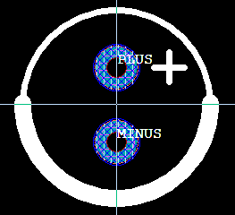
Example 1
CE25-63.shp
This eample contains a typcial example of a through hole component. In this case an anlminium electrolytic capacitor.
Hex view
Hover the mouse over an area to read the value decoded.
| Offset | 0 | 1 | 2 | 3 | 4 | 5 | 6 | 7 | 8 | 9 | A | B | C | D | E | F | | CE25-63.shp| 00000000 | 53 | 68 | 61 | 70 | 65 | 20 | 64 | 65 | 66 | 69 | 6E | 69 | 74 | 69 | 6F | 6E | Shape definition |
| 00000010 | 20 | 31 | 2E | 35 | 00 | 00 | 00 | 00 | 00 | 00 | 00 | 00 | CC | 02 | 00 | 00 | 1.5............ |
| 00000020 | 43 | 45 | 32 | 35 | 2D | 36 | 33 | 00 | 00 | 00 | 00 | 00 | 00 | 00 | 00 | 00 | CE25-63......... |
| 00000030 | 00 | 00 | 00 | 00 | 00 | 00 | 00 | 00 | 00 | 00 | 00 | 00 | 00 | 00 | 00 | 00 | ................ |
| 00000040 | 00 | 00 | 00 | 00 | B4 | 00 | 00 | 00 | 34 | 01 | 00 | 00 | 94 | 01 | 00 | 00 | ........4....... |
| 00000050 | 94 | 01 | 00 | 00 | 01 | 00 | 00 | 00 | 04 | 00 | 00 | 00 | 02 | 00 | 00 | 00 | ................ |
| 00000060 | 00 | 00 | 00 | 00 | 08 | 00 | 00 | 00 | 00 | 00 | 00 | 80 | 00 | 00 | 00 | 00 | ................ |
| 00000070 | 00 | 00 | 00 | 00 | 00 | 00 | 00 | 00 | CC | 02 | 00 | 00 | 02 | 00 | 00 | 00 | ................ |
| 00000080 | 00 | 00 | 00 | 00 | 00 | D4 | 14 | 48 | 00 | 84 | 64 | C8 | 00 | C0 | DA | C6 | .......H..d..... |
| 00000090 | 00 | 00 | 00 | 00 | 00 | 00 | 00 | 00 | 00 | 00 | 00 | 00 | 00 | 13 | 00 | 00 | ................ |
| 000000A0 | 00 | 00 | 00 | 00 | 00 | 00 | 00 | 80 | 00 | CF | 19 | 49 | 00 | 00 | 70 | 41 | ...........I..pA |
| 000000B0 | 00 | 00 | 00 | 00 | 00 | 14 | 00 | 00 | 00 | 00 | 00 | 00 | 00 | 00 | 00 | 00 | ................ |
| 000000C0 | 00 | CF | 19 | 49 | 00 | CF | 19 | 49 | 00 | 24 | 74 | C8 | 00 | 00 | 00 | 00 | ...I...I.$t..... |
| 000000D0 | 00 | 50 | 43 | 48 | 00 | 00 | 00 | 00 | 01 | 60 | 6A | 47 | 00 | 14 | 00 | 00 | .PCH.....`jG.... |
| 000000E0 | 00 | 00 | 00 | 00 | 00 | 00 | 00 | 00 | 00 | CF | 19 | 49 | 00 | CF | 19 | 49 | ...........I...I |
| 000000F0 | 00 | 00 | 00 | 00 | 00 | 24 | F4 | 48 | 00 | 00 | 00 | 00 | 00 | 24 | F4 | 48 | .....$.H.....$.H |
| 00000100 | 00 | 40 | 9C | 46 | 00 | 10 | 00 | 00 | 00 | 24 | F4 | 47 | 00 | 24 | F4 | 47 | .@.F.....$.G.$.G |
| 00000110 | 00 | BA | 5B | 48 | 00 | 24 | F4 | 47 | 00 | 40 | 9C | 46 | 00 | 10 | 00 | 00 | ..[H.$.G.@.F.... |
| 00000120 | 00 | E6 | 2A | 48 | 00 | E6 | 2A | 48 | 00 | E6 | 2A | 48 | 00 | 7C | 92 | 47 | ..*H..*H..*H.|.G |
| 00000130 | 00 | 40 | 9C | 46 | 50 | 4C | 55 | 53 | 00 | 54 | 20 | 54 | 59 | 00 | 01 | 00 | .@.FPLUS.T TY... |
| 00000140 | 00 | 08 | 00 | 00 | FF | FF | FF | FF | 00 | 00 | 00 | 00 | 00 | 24 | F4 | 47 | .............$.G |
| 00000150 | 00 | 7C | 12 | 48 | 00 | B8 | 88 | 47 | 00 | 24 | F4 | 47 | 00 | 9A | 0D | 48 | .|.H...G.$.G...H |
| 00000160 | 00 | 40 | 9C | 46 | 4D | 49 | 4E | 55 | 53 | 00 | 20 | 54 | 59 | 00 | 01 | 00 | .@.FMINUS. TY... |
| 00000170 | 00 | 08 | 00 | 00 | FF | FF | FF | FF | 00 | 00 | 00 | 00 | 00 | 24 | F4 | C7 | .............$.. |
| 00000180 | 00 | 7C | 12 | 48 | 00 | B8 | 88 | 47 | 00 | 24 | F4 | 47 | 00 | 9A | 0D | 48 | .|.H...G.$.G...H |
| 00000190 | 00 | 40 | 9C | 46 | 00 | 14 | 00 | 00 | D0 | 07 | 00 | 00 | 00 | 00 | 00 | 00 | .@.F............ |
| 000001A0 | 00 | 00 | 00 | 00 | 00 | CF | 19 | 49 | 00 | CF | 19 | 49 | 00 | 24 | 74 | C8 | .......I...I.$t. |
| 000001B0 | 00 | 00 | 00 | 00 | 00 | 50 | 43 | 48 | 00 | 00 | 00 | 00 | 01 | 60 | 6A | 47 | .....PCH.....`jG |
| 000001C0 | 00 | 00 | 00 | 00 | 00 | 14 | 00 | 00 | D0 | 07 | 00 | 00 | 00 | 00 | 00 | 00 | ................ |
| 000001D0 | 00 | 00 | 00 | 00 | 00 | CF | 19 | 49 | 00 | CF | 19 | 49 | 00 | 00 | 00 | 00 | .......I...I.... |
| 000001E0 | 00 | 24 | F4 | 48 | 00 | 00 | 00 | 00 | 00 | 24 | F4 | 48 | 00 | 40 | 9C | 46 | .$.H.....$.H.@.F |
| 000001F0 | 00 | 00 | 00 | 00 | 00 | 13 | 00 | 00 | 65 | 00 | 00 | 00 | 00 | 00 | 00 | 00 | ........e....... |
| 00000200 | 00 | 24 | F4 | 47 | 00 | 40 | 1C | 48 | 00 | 00 | 00 | 00 | 00 | 00 | 00 | 00 | .$.G.@.H........ |
| 00000210 | 00 | 00 | 00 | 00 | 00 | 00 | 00 | 00 | 00 | 13 | 00 | 00 | 64 | 00 | 00 | 00 | ............d... |
| 00000220 | 00 | 00 | 00 | 00 | 00 | 24 | F4 | 47 | 00 | 40 | 1C | 48 | 00 | 00 | 00 | 00 | .....$.G.@.H.... |
| 00000230 | 00 | 00 | 00 | 00 | 00 | 00 | 00 | 00 | 00 | 00 | 00 | 00 | 00 | 13 | 00 | 00 | ................ |
| 00000240 | 65 | 00 | 00 | 00 | 00 | 00 | 00 | 00 | 00 | 24 | F4 | C7 | 00 | 40 | 1C | 48 | e........$...@.H |
| 00000250 | 00 | 00 | 00 | 00 | 00 | 00 | 00 | 00 | 00 | 00 | 00 | 00 | 00 | 00 | 00 | 00 | ................ |
| 00000260 | 00 | 13 | 00 | 00 | 64 | 00 | 00 | 00 | 00 | 00 | 00 | 00 | 00 | 24 | F4 | C7 | ....d........$.. |
| 00000270 | 00 | 40 | 1C | 48 | 00 | 00 | 00 | 00 | 00 | 00 | 00 | 00 | 00 | 00 | 00 | 00 | .@.H............ |
| 00000280 | 00 | 00 | 00 | 00 | 00 | 10 | 00 | 00 | D0 | 07 | 00 | 00 | 00 | 24 | F4 | 47 | .............$.G |
| 00000290 | 00 | 24 | F4 | 47 | 00 | BA | 5B | 48 | 00 | 24 | F4 | 47 | 00 | 40 | 9C | 46 | .$.G..[H.$.G.@.F |
| 000002A0 | 00 | 00 | 00 | 00 | 00 | 00 | 00 | 00 | 00 | 10 | 00 | 00 | D0 | 07 | 00 | 00 | ................ |
| 000002B0 | 00 | E6 | 2A | 48 | 00 | E6 | 2A | 48 | 00 | E6 | 2A | 48 | 00 | 7C | 92 | 47 | ..*H..*H..*H.|.G |
| 000002C0 | 00 | 40 | 9C | 46 | 00 | 00 | 00 | 00 | 00 | 00 | 00 | 00 | .@.F........ |
Text view
----[Header section]----
Header
00:1B (char[28]) Identification = Shape definition 1.5
1C:1F (int32) MemSize = 0x02CC
20:3F (char[32]) ShapeName = CE25-63
40:43 (int32) Revision = 0
44:47 (int32) CompOutLineOffset = 0x00B4
48:4B (int32) PinOffset = 0x0134
4C:4F (int32) SilkScreenOffset = 0x0194
50:53 (int32) OtherObjectsOffset = 0x0194
54:57 (int32) NrPlacementOutLines = 1
58:5B (int32) NrCompOutLines = 4
5C:5F (int32) NrPins = 2
60:63 (int32) NrSilkScreenOutLines = 0
64:67 (int32) NrOtherObjects = 8
68:6B (float) InsertionX = 0.0
6C:6F (float) InsertionY = 0.0
70:73 (float) ShapeHeight = 0.0
74:77 (int32) NrPolygons = 0
78:7B (int32) PolygonOffset = 0x02CC
7C:7F (int32) NrLayers = 2
80:83 (int32) Not used
84:87 (float) ShapeNameHeight = 152400.0 (1.524mm)
88:8B (float) ShapeNameOriginX = -234000.0 (-2.34mm)
8C:8F (float) ShapeNameOriginY = -28000.0 (-0.28mm)
90:91 (int16) Info = 0b0000000000000000
92:93 (int16) Not used
94:95 (int16) Not used
96:97 (int16) Not used
98:9B (int32) ShapeNameRotation = 0

----[PlacementOutLines section]----
Object
9C:9F (int32) ObjectType = OBJECT_CIRCLE (0x1300)
A0:A3 (float) X = 0.0
A4:A7 (float) Y = 0.0
A8:AB (float) CircleDiameter = 630000.0 (6.30mm)
AC:AF (float) CircleType = 15.0
B0:B3 (float) Not used

----[CompOutLines section]----
Object
B4:B7 (int32) ObjectType = OBJECT_ARC (0x1400)
B8:BB (float) X = 0.0
BC:BF (float) Y = 0.0
C0:C3 (float) CircleWidth = 630000.0 (6.30mm)
C4:C7 (float) CircleHeight = 630000.0 (6.30mm)
C8:CB (float) StartX = -250000.0 (-2.50mm)
CC:CF (float) StartY = 0.0
D0:D3 (float) EndX = 200000.0 (2.00mm)
D4:D7 (float) EndY = 0.0
D8:DB (float) Thickness = 60000.0039 (0.60mm)

Object
0DC:0DF (int32) ObjectType = OBJECT_ARC (0x1400)
0E0:0E3 (float) X = 0.0
0E4:0E7 (float) Y = 0.0
0E8:0EB (float) CircleWidth = 630000.0 (6.30mm)
0EC:0EF (float) CircleHeight = 630000.0 (6.30mm)
0F0:0F3 (float) StartX = 0.0
0F4:0F7 (float) StartY = 500000.0 (5.00mm)
0F8:0FB (float) EndX = 0.0
0FC:0FF (float) EndY = 500000.0 (5.00mm)
100:103 (float) Thickness = 20000.0 (0.20mm)

Object
104:107 (int32) ObjectType = OBJECT_LINE (0x1000)
108:10B (float) X1 = 125000.0 (1.25mm)
10C:10F (float) Y1 = 125000.0 (1.25mm)
110:113 (float) X2 = 225000.0 (2.25mm)
114:117 (float) Y2 = 125000.0 (1.25mm)
118:11B (float) Thickness = 20000.0 (0.20mm)

Object
11C:11F (int32) ObjectType = OBJECT_LINE (0x1000)
120:123 (float) X1 = 175000.0 (1.75mm)
124:127 (float) Y1 = 175000.0 (1.75mm)
128:12B (float) X2 = 175000.0 (1.75mm)
12C:12F (float) Y2 = 75000.0 (0.75mm)
130:133 (float) Thickness = 20000.0 (0.20mm)

----[Pins section]----
ObjectPin
134:13D (char[10]) PinName = PLUS
13E:13F (int16) NrPinObjects = 1

Object
140:143 (int32) ObjectType = PIN_PUT_THROUGH_ROUND (0x0800)
144:147 (int32) Layer = -1 (not used)
148:14B (float) X = 0.0
14C:14F (float) Y = 125000.0
150:153 (float) OuterDiameter = 150000.0
154:157 (float) DrillDiameter = 70000.0
158:15B (float) InnerDiameter = 125000.0
15C:15F (float) PowerDiameter = 145000.0
160:163 (float) Clearance = 20000.0 (0.20mm)

ObjectPin
164:16D (char[10]) PinName = MINUS
16E:16F (int16) NrPinObjects = 1

Object
170:173 (int32) ObjectType = PIN_PUT_THROUGH_ROUND (0x0800)
174:177 (int32) Layer = -1 (not used)
178:17B (float) X = 0.0
17C:17F (float) Y = -125000.0
180:183 (float) OuterDiameter = 150000.0
184:187 (float) DrillDiameter = 70000.0
188:18B (float) InnerDiameter = 125000.0
18C:18F (float) PowerDiameter = 145000.0
190:193 (float) Clearance = 20000.0 (0.20mm)

----[OtherObjects section]----
Object
194:197 (int32) ObjectType = OBJECT_ARC (0x1400)
198:19B (int32) Layer = SILKSCREEN_TOP_LAYER (2000)
19C:19F (float) X = 0.0
1A0:1A3 (float) Y = 0.0
1A4:1A7 (float) CircleWidth = 630000.0 (6.30mm)
1A8:1AB (float) CircleHeight = 630000.0 (6.30mm)
1AC:1AF (float) StartX = -250000.0 (-2.50mm)
1B0:1B3 (float) StartY = 0.0
1B4:1B7 (float) EndX = 200000.0 (2.00mm)
1B8:1BB (float) EndY = 0.0
1BC:1BF (float) Thickness = 60000.0039 (0.60mm)
1C0:1C3 (float) Clearance = 0.0

Object
1C4:1C7 (int32) ObjectType = OBJECT_ARC (0x1400)
1C8:1CB (int32) Layer = SILKSCREEN_TOP_LAYER (2000)
1CC:1CF (float) X = 0.0
1D0:1D3 (float) Y = 0.0
1D4:1D7 (float) CircleWidth = 630000.0 (6.30mm)
1D8:1DB (float) CircleHeight = 630000.0 (6.30mm)
1DC:1DF (float) StartX = 0.0
1E0:1E3 (float) StartY = 500000.0 (5.00mm)
1E4:1E7 (float) EndX = 0.0
1E8:1EB (float) EndY = 500000.0 (5.00mm)
1EC:1EF (float) Thickness = 20000.0 (0.20mm)
1F0:1F3 (float) Clearance = 0.0

Object
1F4:1F7 (int32) ObjectType = OBJECT_CIRCLE (0x1300)
1F8:1FB (int32) Layer = SOLD_MASK_TOP_LAYER (101)
1FC:1FF (float) X = 0.0
200:203 (float) Y = 125000.0 (1.25mm)
204:207 (float) CircleDiameter = 160000.0 (1.60mm)
208:20B (float) CircleType = 0.0
20C:20F (float) Thickness = 0.0
210:213 (float) Not used
214:217 (float) Clearance = 0.0

Object
218:21B (int32) ObjectType = OBJECT_CIRCLE (0x1300)
21C:21F (int32) Layer = SOLD_MASK_BOTTOM_LAYER (100)
220:223 (float) X = 0.0
224:227 (float) Y = 125000.0 (1.25mm)
228:22B (float) CircleDiameter = 160000.0 (1.60mm)
22C:22F (float) CircleType = 0.0
230:233 (float) Thickness = 0.0
234:237 (float) Not used
238:23B (float) Clearance = 0.0

Object
23C:23F (int32) ObjectType = OBJECT_CIRCLE (0x1300)
240:243 (int32) Layer = SOLD_MASK_TOP_LAYER (101)
244:247 (float) X = 0.0
248:24B (float) Y = -125000.0 (-1.25mm)
24C:24F (float) CircleDiameter = 160000.0 (1.60mm)
250:253 (float) CircleType = 0.0
254:257 (float) Thickness = 0.0
258:25B (float) Not used
25C:25F (float) Clearance = 0.0

Object
260:263 (int32) ObjectType = OBJECT_CIRCLE (0x1300)
264:267 (int32) Layer = SOLD_MASK_BOTTOM_LAYER (100)
268:26B (float) X = 0.0
26C:26F (float) Y = -125000.0 (-1.25mm)
270:273 (float) CircleDiameter = 160000.0 (1.60mm)
274:277 (float) CircleType = 0.0
278:27B (float) Thickness = 0.0
27C:27F (float) Not used
280:283 (float) Clearance = 0.0

Object
284:287 (int32) ObjectType = OBJECT_LINE (0x1000)
288:28B (int32) Layer = SILKSCREEN_TOP_LAYER (2000)
28C:28F (float) X1 = 125000.0 (1.25mm)
290:293 (float) Y1 = 125000.0 (1.25mm)
294:297 (float) X2 = 225000.0 (2.25mm)
298:29B (float) Y2 = 125000.0 (1.25mm)
29C:29F (float) Thickness = 20000.0 (0.20mm)
2A0:2A3 (float) Not used
2A4:2A7 (float) Clearance = 0.0

Object
2A8:2AB (int32) ObjectType = OBJECT_LINE (0x1000)
2AC:2AF (int32) Layer = SILKSCREEN_TOP_LAYER (2000)
2B0:2B3 (float) X1 = 175000.0 (1.75mm)
2B4:2B7 (float) Y1 = 175000.0 (1.75mm)
2B8:2BB (float) X2 = 175000.0 (1.75mm)
2BC:2BF (float) Y2 = 75000.0 (0.75mm)
2C0:2C3 (float) Thickness = 20000.0 (0.20mm)
2C4:2C7 (float) Not used
2C8:2CB (float) Clearance = 0.0
Example 2
polygons.shp
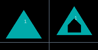
This is a minimal example to show how polygons are stored. It contains only two trianglular polygons on the top copper layer. The polygon on the left is a normal polygon, the polygonon the right contains 1 pentagonal SubPolygon (cutout).
Hex view
Hover the mouse over an area to read the value decoded.
| Offset | 0 | 1 | 2 | 3 | 4 | 5 | 6 | 7 | 8 | 9 | A | B | C | D | E | F | | polygons.shp| 00000000 | 53 | 68 | 61 | 70 | 65 | 20 | 64 | 65 | 66 | 69 | 6E | 69 | 74 | 69 | 6F | 6E | Shape definition |
| 00000010 | 20 | 32 | 2E | 30 | 00 | 00 | 00 | 00 | 00 | 00 | 00 | 00 | 90 | 02 | 00 | 00 | 2.0............ |
| 00000020 | 70 | 6F | 6C | 79 | 67 | 6F | 6E | 73 | 00 | 00 | 00 | 00 | 00 | 00 | 00 | 00 | polygons........ |
| 00000030 | 00 | 00 | 00 | 00 | 00 | 00 | 00 | 00 | 00 | 00 | 00 | 00 | 00 | 00 | 00 | 00 | ................ |
| 00000040 | 00 | 00 | 00 | 00 | 9C | 00 | 00 | 00 | 9C | 00 | 00 | 00 | F0 | 00 | 00 | 00 | ................ |
| 00000050 | F0 | 00 | 00 | 00 | 00 | 00 | 00 | 00 | 00 | 00 | 00 | 00 | 01 | 00 | 00 | 00 | ................ |
| 00000060 | 00 | 00 | 00 | 00 | 00 | 00 | 00 | 00 | 00 | 00 | 00 | 00 | 00 | 00 | 00 | 00 | ................ |
| 00000070 | 00 | 00 | 00 | 00 | 02 | 00 | 00 | 00 | F0 | 00 | 00 | 00 | 02 | 00 | 00 | 00 | ................ |
| 00000080 | 00 | 00 | 00 | 00 | 00 | D4 | 14 | 48 | 00 | 00 | 00 | 00 | 00 | 00 | 00 | 00 | .......H........ |
| 00000090 | 00 | 01 | 00 | 00 | 00 | 00 | 00 | 00 | 00 | 00 | 00 | 00 | 31 | 00 | 00 | 00 | ............1... |
| 000000A0 | 00 | 00 | 00 | 00 | 00 | 00 | 02 | 00 | B0 | 09 | 00 | 00 | 01 | 00 | 00 | 00 | ................ |
| 000000B0 | 00 | E6 | 2A | C9 | 00 | 24 | F4 | 48 | 00 | 00 | 00 | 00 | 00 | 00 | 00 | 00 | ..*..$.H........ |
| 000000C0 | F0 | 00 | 00 | 00 | 00 | 00 | 00 | 00 | 00 | 00 | 00 | 00 | B0 | 09 | 00 | 00 | ................ |
| 000000D0 | 01 | 00 | 00 | 00 | 00 | 50 | 43 | 48 | 00 | 50 | 43 | 48 | 00 | 00 | 00 | 00 | .....PCH.PCH.... |
| 000000E0 | 00 | 00 | 00 | 00 | 80 | 01 | 00 | 00 | 00 | 00 | 00 | 00 | 00 | 00 | 00 | 00 | ................ |
| 000000F0 | 00 | 08 | 00 | 00 | 00 | 00 | 01 | 00 | 01 | 00 | 00 | 00 | 00 | 00 | 00 | 00 | ................ |
| 00000100 | 03 | 00 | 00 | 00 | 00 | 00 | 00 | 00 | C0 | 00 | 00 | 00 | 00 | 00 | 00 | 00 | ................ |
| 00000110 | 00 | 00 | 00 | 00 | 00 | 00 | 00 | 00 | 00 | 00 | 00 | 00 | 00 | 00 | 00 | 00 | ................ |
| 00000120 | 00 | 00 | 00 | 00 | C0 | 5C | 25 | C1 | 00 | 00 | 00 | 00 | 80 | 84 | 1E | 41 | .....\%........A |
| 00000130 | 00 | 00 | 00 | 00 | 80 | 84 | 1E | C1 | 00 | 00 | 00 | 00 | 00 | 6A | 18 | C1 | .............j.. |
| 00000140 | 00 | 00 | 00 | 00 | 80 | 84 | 1E | 41 | 00 | 00 | 00 | 00 | 00 | 6A | 18 | 41 | .......A.....j.A |
| 00000150 | 00 | 00 | 00 | 00 | 80 | 84 | 1E | 41 | 00 | 00 | 00 | 00 | 00 | 6A | 18 | C1 | .......A.....j.. |
| 00000160 | 00 | 00 | 00 | 00 | 00 | 00 | 00 | 00 | 00 | 00 | 00 | 00 | 00 | 6A | 18 | 41 | .............j.A |
| 00000170 | 00 | 00 | 00 | 00 | 80 | 84 | 1E | C1 | 00 | 00 | 00 | 00 | 00 | 6A | 18 | C1 | .............j.. |
| 00000180 | 00 | 08 | 00 | 00 | 00 | 00 | 00 | 00 | 01 | 00 | 00 | 00 | 00 | 00 | 00 | 00 | ................ |
| 00000190 | 0B | 00 | 00 | 00 | 00 | 00 | 00 | 00 | 00 | 00 | 00 | 00 | 00 | 00 | 00 | 00 | ................ |
| 000001A0 | 01 | 00 | 00 | 00 | 03 | 00 | 00 | 00 | 00 | 00 | 00 | 00 | 00 | 00 | 00 | 00 | ................ |
| 000001B0 | 00 | 00 | 00 | 00 | 00 | 00 | 00 | 00 | 00 | 00 | 00 | 00 | 00 | 00 | 00 | 00 | ................ |
| 000001C0 | 00 | 00 | 00 | 00 | 00 | 00 | 00 | 00 | 00 | 00 | 00 | 00 | 00 | 00 | 00 | 00 | ................ |
| 000001D0 | 00 | 00 | 00 | 00 | 80 | 84 | 2E | 41 | 00 | 00 | 00 | 00 | 00 | 6A | 28 | 41 | .......A.....j(A |
| 000001E0 | 00 | 00 | 00 | 00 | 00 | 00 | 00 | 00 | 00 | 00 | 00 | 00 | 00 | 00 | 00 | 00 | ................ |
| 000001F0 | 00 | 00 | 00 | 00 | 80 | 84 | 2E | 41 | 00 | 00 | 00 | 00 | 00 | 00 | 00 | 00 | .......A........ |
| 00000200 | 00 | 00 | 00 | 00 | 80 | 84 | 1E | 41 | 00 | 00 | 00 | 00 | 00 | 6A | 28 | 41 | .......A.....j(A |
| 00000210 | 2C | 8E | CB | 44 | 05 | 00 | 00 | 00 | 00 | 00 | 00 | 00 | 00 | 00 | 00 | 00 | ,..D............ |
| 00000220 | 00 | 00 | 00 | 00 | 00 | 88 | 13 | 41 | 00 | 00 | 00 | 00 | 00 | 88 | F3 | 40 | .......A.......@ |
| 00000230 | 00 | 00 | 00 | 00 | 80 | C0 | 24 | 41 | 00 | 00 | 00 | 00 | 80 | 13 | 1C | 41 | ......$A.......A |
| 00000240 | 00 | 00 | 00 | 00 | 00 | 88 | 13 | 41 | 00 | 00 | 00 | 00 | 00 | 17 | 11 | 41 | .......A.......A |
| 00000250 | 00 | 00 | 00 | 00 | 80 | 84 | 1E | 41 | 00 | 00 | 00 | 00 | 80 | 13 | 1C | 41 | .......A.......A |
| 00000260 | 00 | 00 | 00 | 00 | 80 | C0 | 24 | 41 | 00 | 00 | 00 | 00 | 00 | 17 | 11 | 41 | ......$A.......A |
| 00000270 | 00 | 00 | 00 | 00 | 80 | C0 | 24 | 41 | 00 | 00 | 00 | 00 | 00 | 88 | F3 | 40 | ......$A.......@ |
| 00000280 | 00 | 00 | 00 | 00 | 00 | 88 | 13 | 41 | 00 | 00 | 00 | 00 | 00 | 88 | F3 | 40 | .......A.......@ |
Text view
----[Header section]----
Header
00:1B (char[28]) Identification = Shape definition 2.0
1C:1F (int32) MemSize = 0x0290
20:3F (char[32]) ShapeName = polygons
40:43 (int32) Revision = 0
44:47 (int32) CompOutLineOffset = 0x009C
48:4B (int32) PinOffset = 0x009C
4C:4F (int32) SilkScreenOffset = 0x00F0
50:53 (int32) OtherObjectsOffset = 0x00F0
54:57 (int32) NrPlacementOutLines = 0
58:5B (int32) NrCompOutLines = 0
5C:5F (int32) NrPins = 1
60:63 (int32) NrSilkScreenOutLines = 0
64:67 (int32) NrOtherObjects = 0
68:6B (float) InsertionX = 0.0
6C:6F (float) InsertionY = 0.0
70:73 (float) ShapeHeight = 0.0
74:77 (int32) NrPolygons = 2
78:7B (int32) PolygonOffset = 0x00F0
7C:7F (int32) NrLayers = 2
80:83 (int32) Not used
84:87 (float) ShapeNameHeight = 152400.0 (1.524mm)
88:8B (float) ShapeNameOriginX = 0.0
8C:8F (float) ShapeNameOriginY = 0.0
90:91 (int16) Info = SMT flag 1 (0b0000000100000000)
92:93 (int16) Not used
94:95 (int16) Not used
96:97 (int16) Not used
98:9B (int32) ShapeNameRotation = 0

----[Pins section]----
ObjectPin
09C:0AB (char[10]) PinName = 1
0A6:0A7 (int16) NrPinObjects = 2

Object
0A8:0AB (int32) ObjectType = PIN_SMD_POLYGON (0x09B0)
0AC:0AF (int32) Layer = 1 (top copper)
0B0:0B3 (float) X = -700000.0 (-7.00mm)
0B4:0B7 (float) Y = 500000.0 (5.00mm)
0B8:0BB (float) Not used
0BC:0BF (float) Not used
0C0:0C3 (uint32) PolygonPointer = 0x00F0
0C4:0C7 (float) Not used
0C8:0CB (float) Clearance = 0.0

Object
0CC:0CF (int32) ObjectType = PIN_SMD_POLYGON (0x09B0)
0D0:0D3 (int32) Layer = 1 (top copper)
0D4:0D7 (float) X = 200000.0 (2.00mm)
0D8:0DB (float) Y = 200000.0 (2.00mm)
0DC:0DF (float) Not used
0E0:0E3 (float) Not used
0E4:0E7 (uint32) PolygonPointer = 0x0180
0E8:0EB (float) Not used
0EC:0EF (float) Clearance = 0.0

----[Polygons section]----
ObjectPolygon
0F0:0F1 (int16) Not used
0F2:0F3 (int16) Not used
0F4:0F5 (int16) Not used
0F6:0F7 (int16) Not used
0F8:0FB (int32) Layer = 1 (top copper)
0FC:0FF (int32) PinNr = 0
100:103 (int32) NrVertices = 3
104:107 (int32) PolygonNr = 0
108:10B (int32) ShapePolygonPosition = 0x00C0
10C:10F (float) Clearance = 0.0
110:113 (int32) NrSubPolygons = 0
114:117 (int32) NrVerticesMainPolygon = 0
118:11B (int32) Not used
11C:11F (int32) Not used
120:127 (double) OffsetX = -700000.0 (-7.00mm)
128:12F (double) OffsetY = 500000.0 (5.00mm)
130:137 (double) minX = -500000.0 (-5.00mm)
138:13F (double) minY = -400000.0 (-4.00mm)
140:147 (double) maxX = 500000.0 (5.00mm)
148:14F (double) maxY = 400000.0 (4.00mm)

ObjectPoint
150:157 (double) PointX0 = 500000.0 (5.00mm)
158:15F (double) PointY0 = -400000.0 (-4.00mm)

ObjectPoint
160:167 (double) PointX1 = 0.0
168:16F (double) PointY1 = 400000.0 (4.00mm)

ObjectPoint
170:177 (double) PointX2 = -500000.0 (-5.00mm)
178:17F (double) PointY2 = -400000.0 (-4.00mm)

ObjectPolygon
180:181 (int16) Not used
182:183 (int16) Not used
184:185 (int16) Not used
186:187 (int16) Not used
188:18B (int32) Layer = 1 (top copper)
18C:18F (int32) PinNr = 0
190:193 (int32) NrVertices = 11
194:197 (int32) PolygonNr = 0
198:19B (int32) ShapePolygonPosition = 0
19C:19F (float) Clearance = 0.0
1A0:1A3 (int32) NrSubPolygons = 1
1A4:1A7 (int32) NrVerticesMainPolygon = 3
1A8:1AB (int32) Not used
1AC:1AF (int32) Not used
1B0:1B7 (double) OffsetX = 0.0
1B8:1BF (double) OffsetY = 0.0
1C0:1C7 (double) minX = 0.0
1C8:1CF (double) minY = 0.0
1D0:1D7 (double) maxX = 1000000.0 (10.00mm)
1D8:1DF (double) maxY = 800000.0 (8.00mm)

ObjectPoint
1E0:1E7 (double) PointX0 = 0.0
1E8:1EF (double) PointY0 = 0.0

ObjectPoint
1F0:1F7 (double) PointX1 = 1000000.0 (10.00mm)
1F8:1FF (double) PointY1 = 0.0

ObjectPoint
200:207 (double) PointX2 = 500000.0 (5.00mm)
208:20F (double) PointY2 = 800000.0 (8.00mm)

ObjectSubPolygon
210:213 (int32) 0x44CB8E2C (magic number)
214:217 (int32) NrVertices = 5
218:21B (int32) Not used
21C:21F (int32) Not used
220:227 (double) minX = 320000.0 (3.20mm)
228:22F (double) minY = 80000.0 (0.80mm)
230:237 (double) maxX = 680000.0 (6.80mm)
238:23F (double) maxY = 460000.0 (4.60mm)

ObjectPoint
240:247 (double) PointX0 = 320000.0 (3.20mm)
248:24F (double) PointY0 = 280000.0 (2.80mm)

ObjectPoint
250:257 (double) PointX1 = 500000.0 (5.00mm)
258:25F (double) PointY1 = 460000.0 (4.60mm)

ObjectPoint
260:267 (double) PointX2 = 680000.0 (6.80mm)
268:26F (double) PointY2 = 280000.0 (2.80mm)

ObjectPoint
270:277 (double) PointX3 = 680000.0 (6.80mm)
278:27F (double) PointY3 = 80000.0 (0.80mm)

ObjectPoint
280:287 (double) PointX4 = 320000.0 (3.20mm)
288:28F (double) PointY4 = 80000.0 (0.80mm)